This is a part of my on-and-off explorations into Fujifilm's digital medium format G-mount protocol.
- Sniffing the Fujifilm G-mount lens-body communications
- Custom GF adapter for S35 MK Cine-zooms
- Learning from GF lens firmware updates
- Driving Fuji G lenses from DIY hardware
A rocky start
I've been working on a personal project where I need computer control over the focus and zoom of a lens for each frame of a timelapse. The first step was to get the optics sorted out.
In late 2023 I was lucky enough to find an incredible deal on a pair of Fujinon MK Zooms (18-55 T2.9, 55-135 T2.9). The most obvious difference between normal photo lenses and 'cinema glass' intended for video use is the focus and zoom rings have a wider rotation range and teeth to interface with external geared FIZ (Focus, Iris, Zoom) knobs or motors.
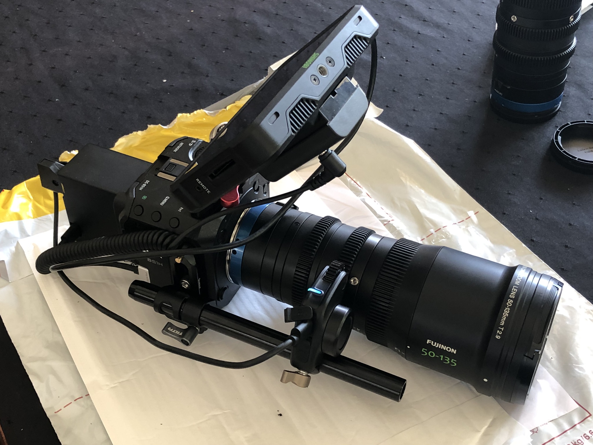
These lenses should be a great fit for the project, but these MK zooms aren't directly compatible with the pile of camera gear on-hand.
Something that's often surprising to photographers is how often cinema lenses are pulled apart to change the lens mount or to correct for back-focus tolerance issues by shimming (adding or subtracting thin spacers).
Thankfully these lenses are popular enough to attract the cottage industry manufacturing alternative lens mounts. These lenses had actually already been adapted from their native Sony E mount to Canon RF mount by the supplier, and I swapped them to L-mount using a MTF Services conversion kit for use on the Panasonic BS1-H for video work.
While I've previously praised the Panasonic BS1-H for it's dedication to video functionality and pseudo-pro IO, it can't take photos! To make things harder, there aren't any L-mount bodies at local rental houses.
The options are to buy a whole L or RF mount camera for a single timelapse shot, or find another way.
A Crazy Alternative?
Adapting the MK zooms between their native Sony E mount, Leica L, and Canon RF mounts is possible because the flange distances are similar enough that the adapter only needs to provide a mechanically compatible bayonet to interface with the camera.
When a lens is designed for a flange distance that's longer than the mount, the adapter also acts as a spacer to achieve the same effective distance to the sensor. This is why older lenses for mirrored SLR cameras are so easily adapted to the newer generation of mirrorless bodies.
My stills camera is a Fuji GFX50R, and the G mount's (relatively) short 26.7 mm flange depth makes it an easy target to adapt older medium format (and some 35 mm) lenses, but it's far too long for a lens intended for more typical full-frame mirrorless bodies.
However, when I was changing lenses I realised the back half of the zooms felt small enough that it could be recessed into the GFX's mount.
Armed with some calipers, the Fuji extension tube as a stand-in for the camera, MC-21 EF to L adapter acting as a mock lens, I could check the fitment without risking an expensive camera or lens.
The parts seem to fit well enough that ~6mm of depth could be reclaimed, but it's a very tight fit.
This approach is pretty interesting, as I've been itching for an opportunity to test custom mount designs after I started reverse-engineering of the Fujifilm 'medium format' G mount a few years ago.
Could this actually work?
The MK zooms have an image circle of ~28.5 mm designed for the typical Super-35 format 24.8x18.6 mm. The G mount is designed for a larger 43.9x32.9 mm format, more than 4x the imaging area.
TODO: Diagram showing size difference in image circle and format size.
Because the G mount is designed for a large sensor it needs a wider optical path, resulting in a fairly massive internal diameter (throat) of ~56 mm. The zoom's have an exterior diameter of 65 mm near the mount, not large enough to fit inside the G mount unmodified, but not too far off either.
There are some immediately obvious design details that are rather critical:
- The rear collar of the MK zoom needs to be replaced, thinning the lens body to be smaller than the internal diameter of the camera's body mount,
- Correcting the flange distance offset requires the lens to move ~6 mm closer to the sensor, so we need to check there's enough depth to work with.
- The zoom still needs to be securely mounted to the body for support to be usable, ideally without external support structures.
Pulling the rear-most collar off the lens, we can see a lip and alignment face along with an array of holes around the cylinder for both threaded screws and some grub-screws. The grub-screws are tightened after the lens mount is assembled to allow force transmission between the lens mount and lens through the collar rather than the small rear mounting screws. These features need to be replicated in the adapter.
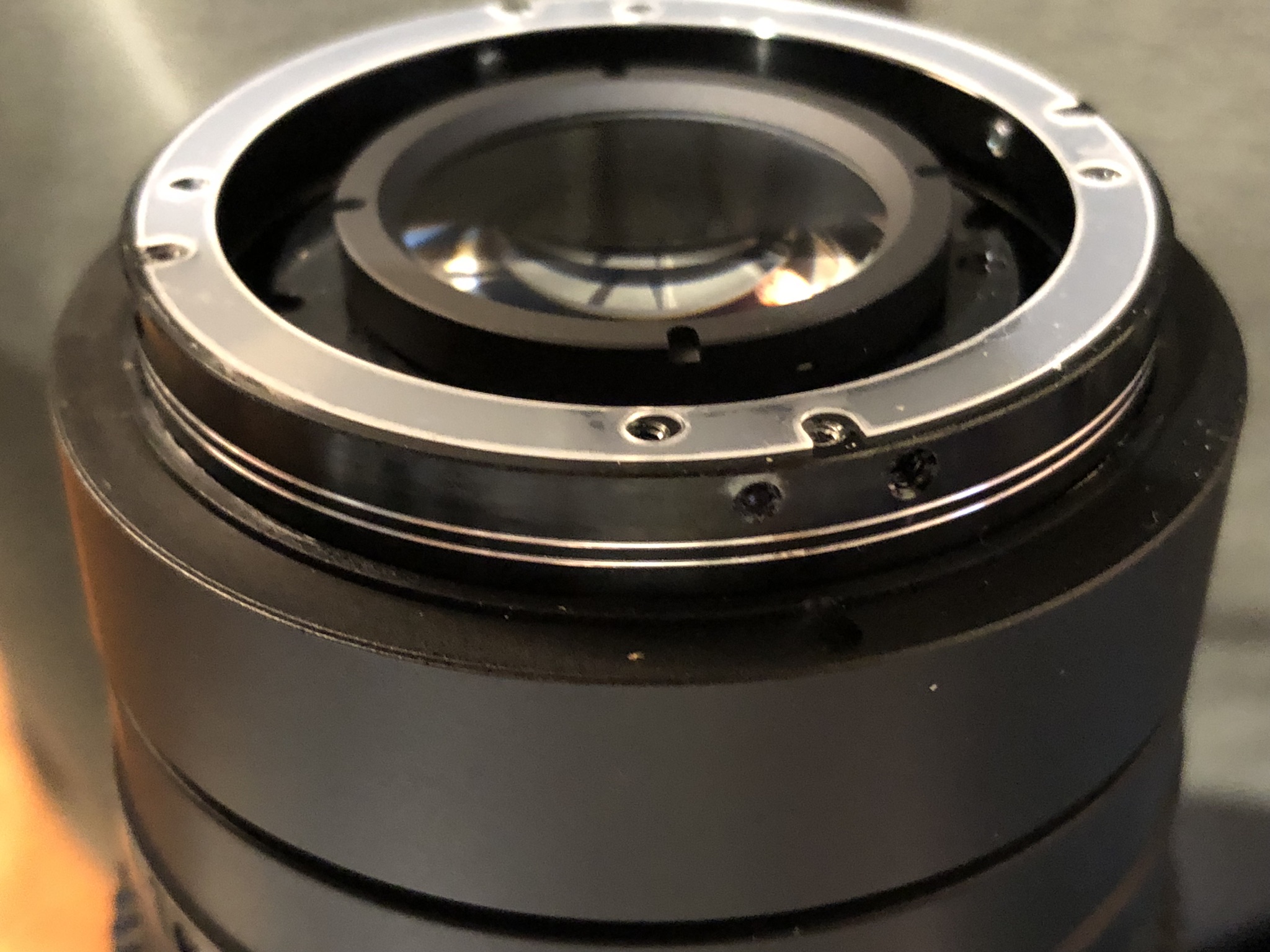
The lenses' rear element groups also aren't mechanically static, they move in and out for zoom and the macro toggle which can increase the depth requirement.
Thankfully there's a reasonable amount of room between the sensor and the lens mount, but I did learn there's a large sheet of protective glass mounted to the back of the rectangular baffle, quite far from the sensor.
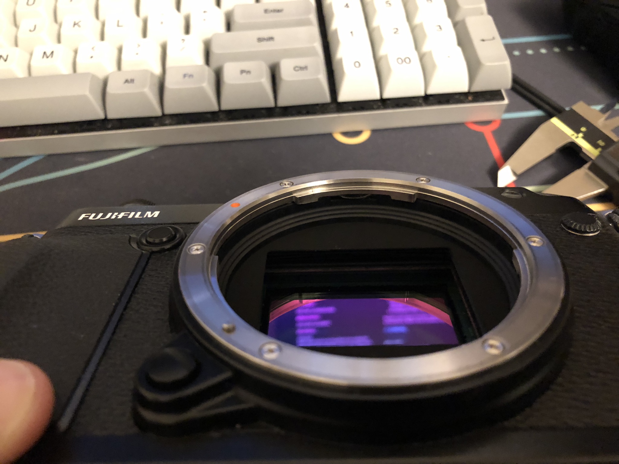
Don't worry - I measured the available room safely with a soft plastic stick as the depth gauge rather than sticking metal calipers directly into the body!
Prototype
Spending an evening with a pair of calipers and Solidworks gave me a fairly accurate 3D model of the MK zooms. Most of the time was spent carefully capturing the detail of the internal geometry around the rear elements and mount section.
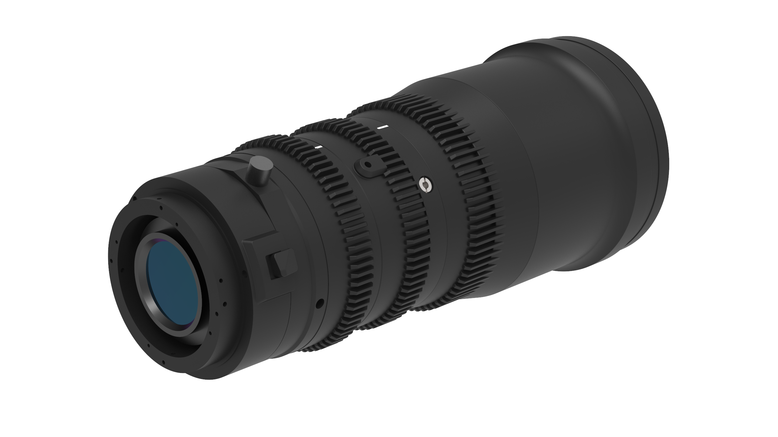
Because I already had 3D models for both sides of the Fuji G mount as part of some prior reverse engineering, mocking the mount arrangement quickly let me check that parts would actually clear each other.
The resulting concept design is a custom rear collar which replaces the last section of the lens (the blue ring in earlier photos).
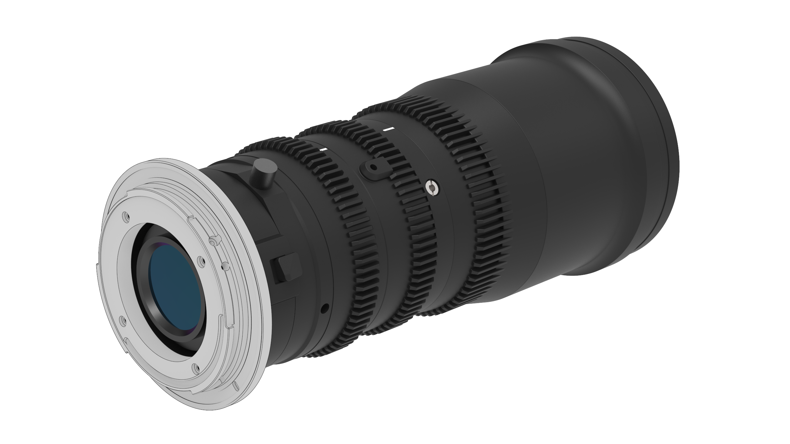
With the single piece design acting as the collar and the G mount, the lens can sit inside the GFX by 6.5 mm to correctly compensate for the longer flange distance.
The biggest challenge was orienting and aligning the handful of small screws and grub-screws which radially load against the MK's frame. The G mount normally attaches to the lens with screws pointing 'down the barrel' of the lens.
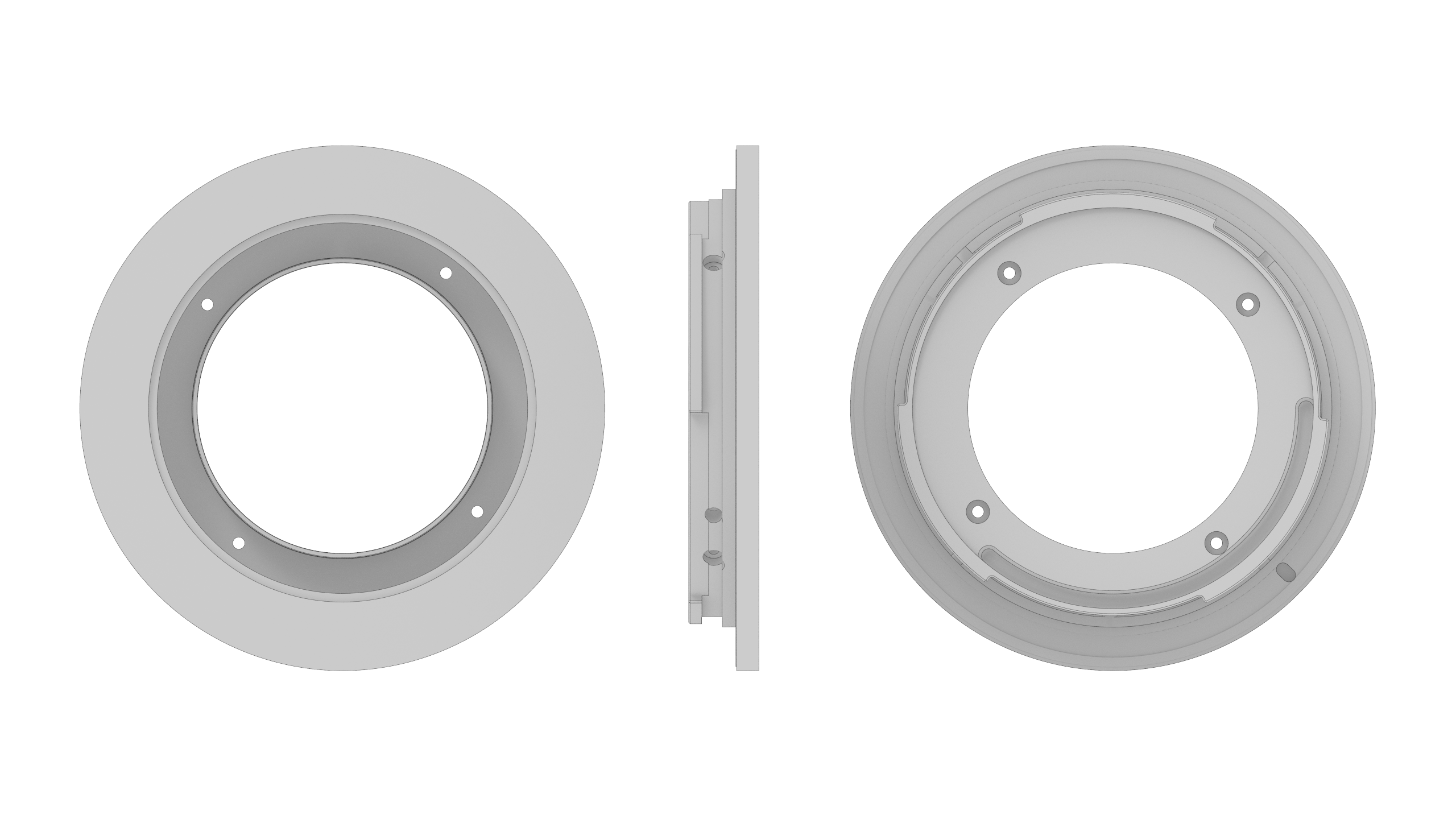
At this point everything was looking good on screen, so I ordered a few 3D printed prototypes. I opted for SLA printing to hit the fine tolerances I needed, with the understanding that they're only strong enough for a test-fit.
A week later, they arrived and I carefully test-fit one on the 18-55. Shockingly, everything lined up perfectly and I had a workable concept.
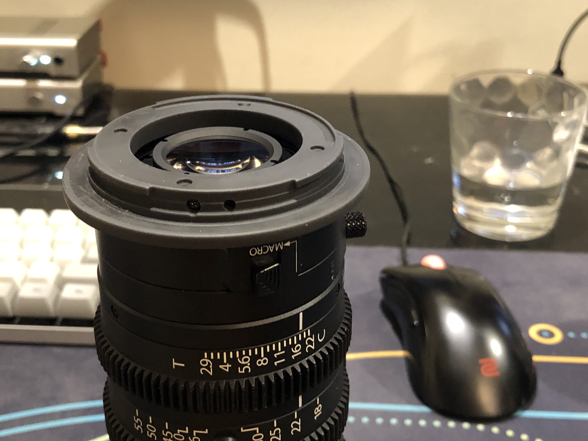
Worried about tolerance issues causing a jam when mounted to the camera, I quickly tested a second printed adapter with the MCEX extension tube. It also entered and left the mount without issue, so I took the plunge and mounted it to the 50R.
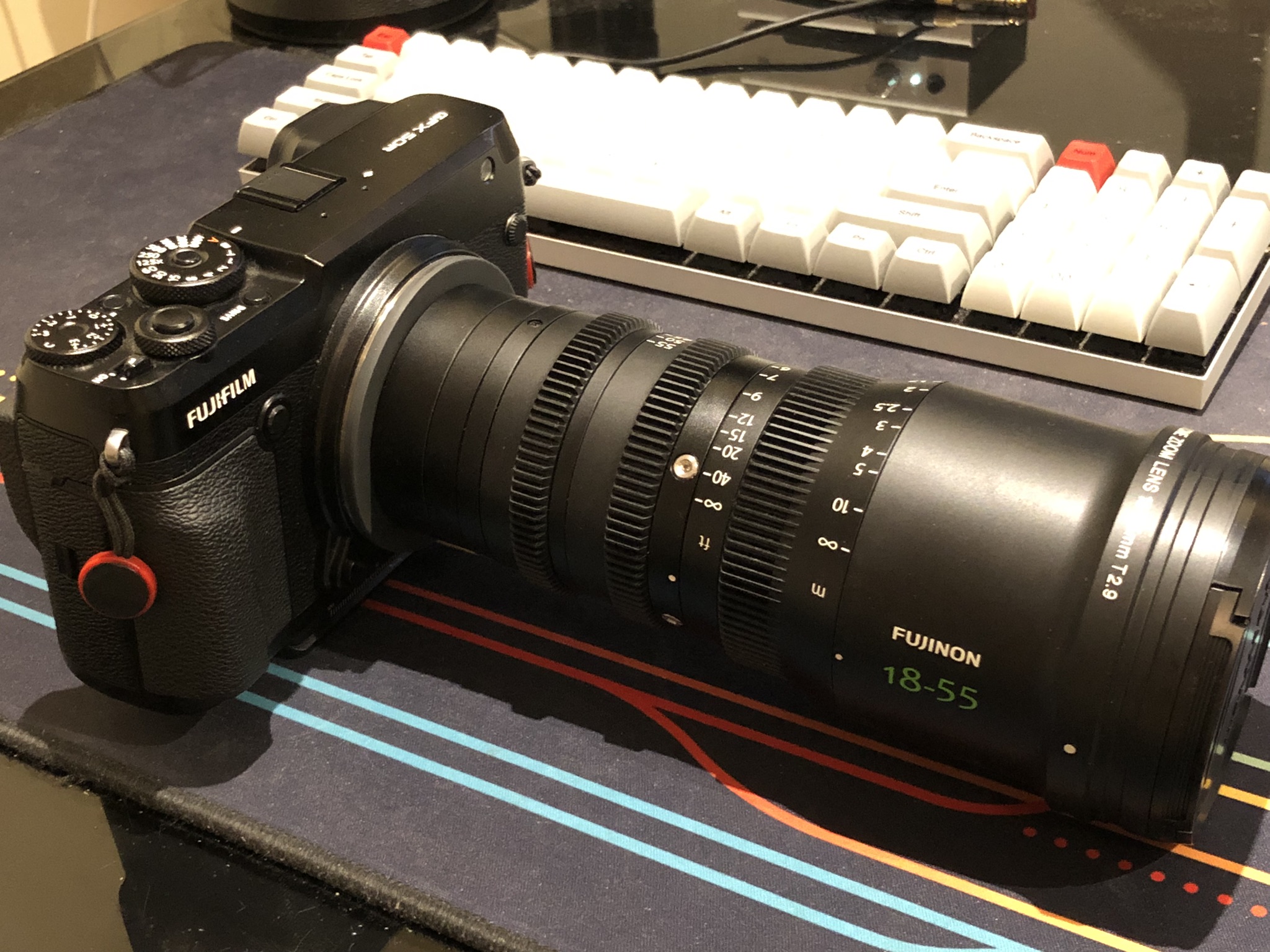
It was also great to use this as validation for the reverse engineered G mount geometry.
Either the flange distance calculations and tolerancing were spot-on or I got lucky, but the full range of focus to infinity looked sharp, and the MK 'macro' toggle also works perfectly.
When the zoom is set on the longer half the resulting image circle is larger than I expected, giving a pretty usable 6K resolution when cropping a clean 16:9 frame from the raw image.
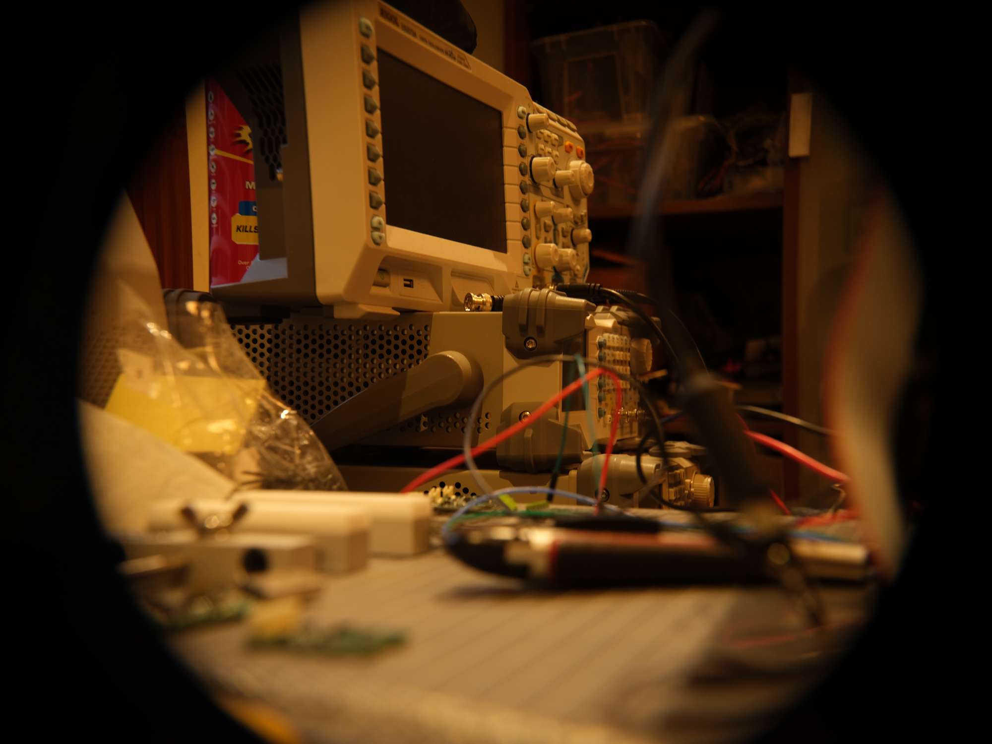
On the wider end the circle shrinks, the corners get worse, and a tighter crop is needed but is still usable. Given 18 mm is incredibly wide, it's not likely that range will see much use anyway.
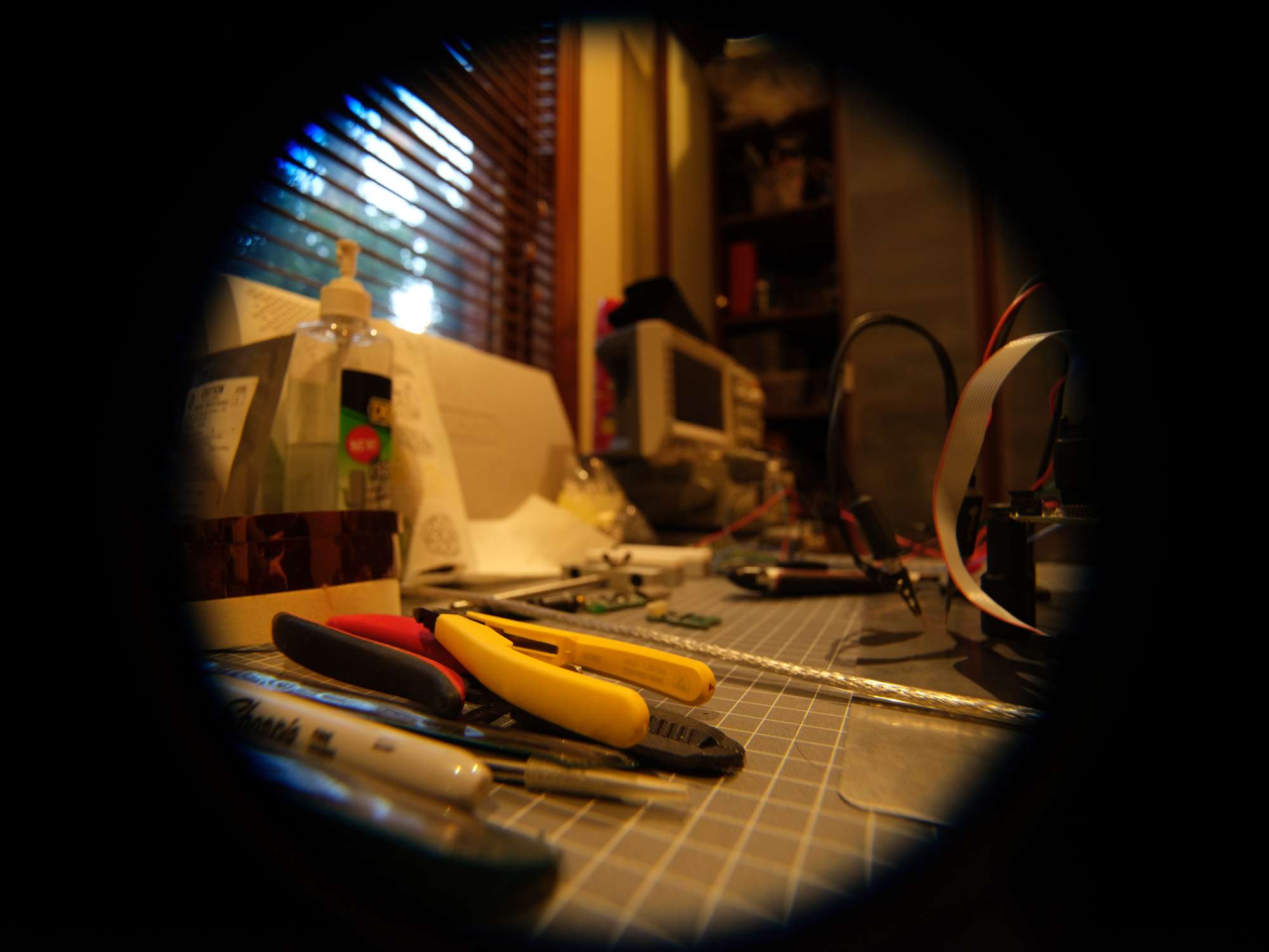
With only some sub-millimeter tweaks needed to tidy up a few mounting hole alignments, I considered the design ready to prototype with a more robust material.
CNC Machining
I'm not equipped with the tools to manufacture a complex part like this, but the recent accessibility of low-cost Chinese CNC prototyping houses makes this process far more approachable.
Up to this point, just getting the geometry to make sense was the priority and good 3D printers let you mostly skip over design optimisations for prototypes, but some minimal DFM (design-for-manufacture) thought before cutting metal makes sense
- Thinking about how a part will be machined helps you see which design features might be more important than others.
- This part could be turned with a lathe, using either live tooling or a post-drilling stage for the odd side bores.
- Most features could be handled by a 4+ axis mill and two setups,
- Or if the manufacturer has excess machines and time they might even produce a one-off prototype with an EDM process.
- Critical tolerances or surface finishes matter a lot, the bayonet mount has several faces that see sliding metal-on-metal contact
- Material choice isn't as critical for a 'one-off' prototype, but lens mounts are often nickel plated brass.
- Some materials narrow what machining processes can be used, or what post-processing is available
- Changes the compromises between cost, durability, machinability, galling resistance
- Some materials would be harder to 'fix' with hand-tools if there are issues with tolerances
- An engineering plastic like POM (acetal) would actually be fine for this one-off as well
- If I were making more than one, I'd probably aim for a basic brass alloy like H59 or maybe even an aluminium
Given we don't necessarily know what approach a random prototyping house will use, we'll stick to generic improvements that would help regardless of process. The low-hanging fruit is some small details which the printed prototype inherited directly from the reverse-engineered G mount model.
- Removed some small features which were artifacts of Fujifilm's manufacturing process,
- Tweaked the positions of the 4 rear face screws slightly
- Increased thickness of the rear face and the internal sleeve.
- Drawing call-outs to allow some optional radii for flexibility between machining approaches.
I sent the file and drawing off for a quote in a few different materials and got a response the next day.
There was barely any cost difference between plastic, aluminium and brass, and basic bead-blasting or anodizing services were also nearly free. So I paid my AUD$70 + 35 for freight, and a week later the part arrived.
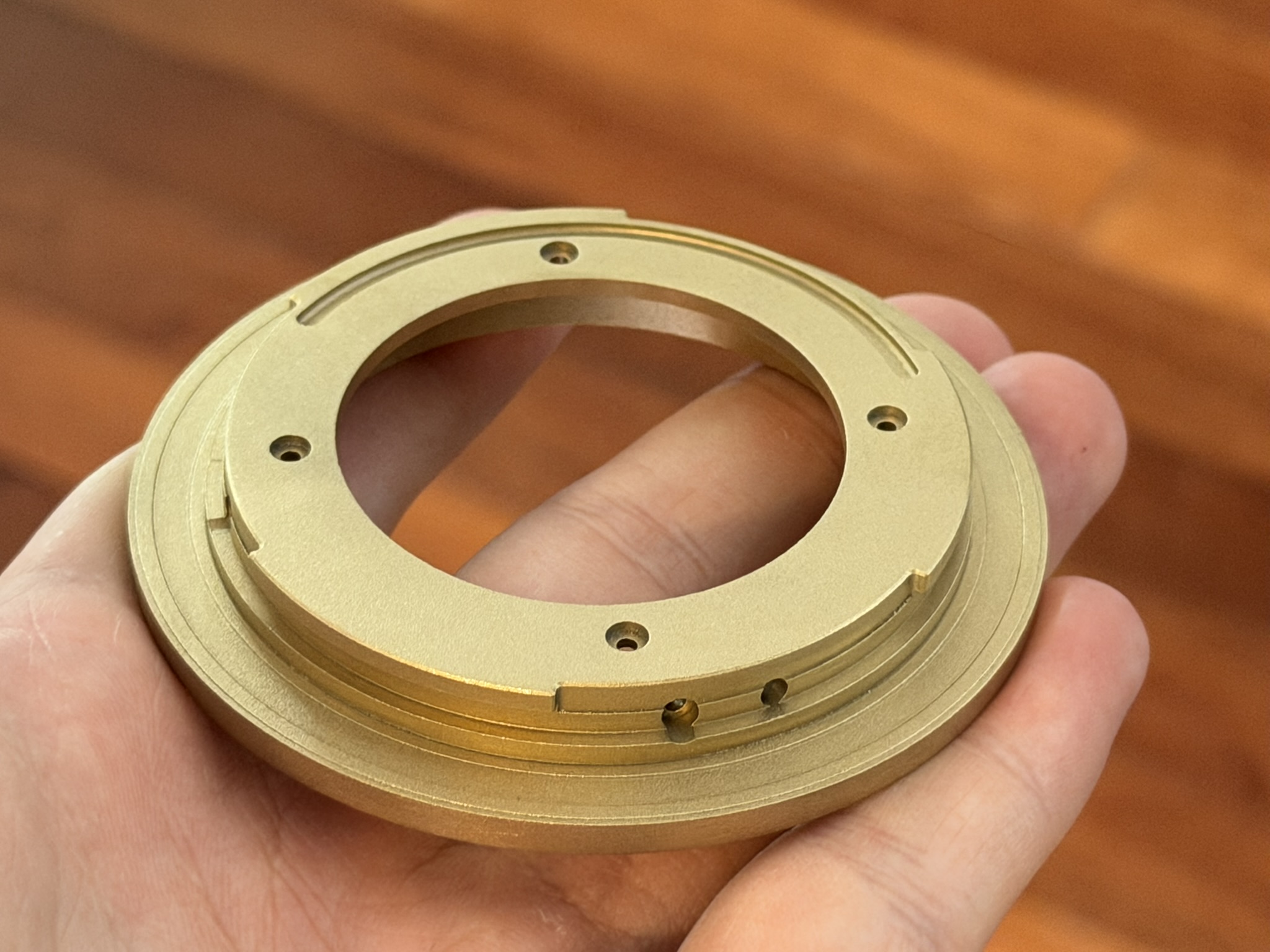
It looks pretty good, but how it measures against the drawing is more important.
Test fitting against the macro tube showed a problem, the bayonet could enter the mount, but was too tight to twist or come out easily if there was any rotation during insertion. The diameter of an outer ring was too tight.
TODO:
Render out/embed a image with call-outs showing the inner ring that's slightly oversized - measurements vs model
Describe how I reduced the diameter by hand
Find the photos of it mounted and embed
Closing
I didn't go into this conversion knowing it would be so effective, given how unusual it is to adapt smaller lenses to larger format sensors.
I don't expect anyone else to replicate my work, but the project files are available on GitHub. Follow at your own risk etc.
This would look rather hilarious mounted to the Eterna camera. Anyone have access to one in South Australia?
If you have questions or find anything useful here, let me know!